

Virtual Local Area Networks or in the shortened form (abbreviation), VLAN is one of the most fundamental concepts and methodologies in Computer Networking which allows the segmentation the physical network of a LAN into separate logical networks. Before VLANs, Local Area Network (LAN) is a group of interconnected devices within the same broadcast domain. Networks in houses, schools, offices are examples of LANs. The following figure contains an example topology of a LAN.
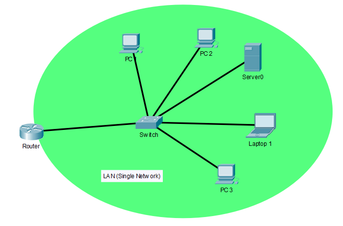
A LAN can be a wired network using copper ethernet cables, fiber optics or wireless network which communicates using high-frequency radio waves (most commonly, Wi-Fi) or a mix of both ways. LAN is basically the physical network topology that can be geographically spanned to 1-1000 meter radius. In a LAN, all the end-user devices (PCs, Servers etc) usually connect to switches and finally, all the switches connect to one router or multiple routers for redundancy. The router is the network device that allows the end devices (end nodes) to establish communication with the internet or any other connected network as a Wide Area Network (WAN). The connectivity beyond the router is not related to the LAN and the communication process of a router is called Routing. Therefore the majority of jobs in a LAN connectivity are done by the switches and that communication process is called Switching.
Still, all the devices which belong to the LAN are in the same broadcast domain. All the broadcast messages originated from switches will be reached to all network and end devices of the LAN. As a result of that, slow network performance and security issues may occur in the LAN. More importantly, all the end devices in the LAN can establish a connection between each other without any rules and regulations unless the switches are not configured with Access Control Lists (ACLs). However, in the modern corporate networking arena, this is not a good condition because corporates always enforce network usage policies to their employees and these policies applied to each employee in different manners such as according to the functions performed by the employee, the department that the employee belongs to, the applications used by the employee etc. Segmentation of end devices/users into different networks is the best solution for this situation. LAN segmentation or separation can be implemented in two ways. They are,
- Physical LAN Segmentation (Traditional way)
- VLAN Segmentation (Virtual way)
Physical LAN Segmentation
In order to perform this kind of grouping in the network level, the network architect or engineer or whoever the design the network has to allocate end nodes into different IP networks which connect to different router ports. This also requires the physical separation of cabling for each network, if it is a wired network. Dealing with a separate physical network will be a real mess when it comes to medium or large enterprise offices because employees belong to different departments can be work together in the same room, even the same department employees can have different network requirements. On the other hand, this will need higher maintenance and using a separate router port for many groups will not be a cost-effective movement because of the router ports are very expensive network accessories. A traditional LAN segmentation in a small office building is shown below.
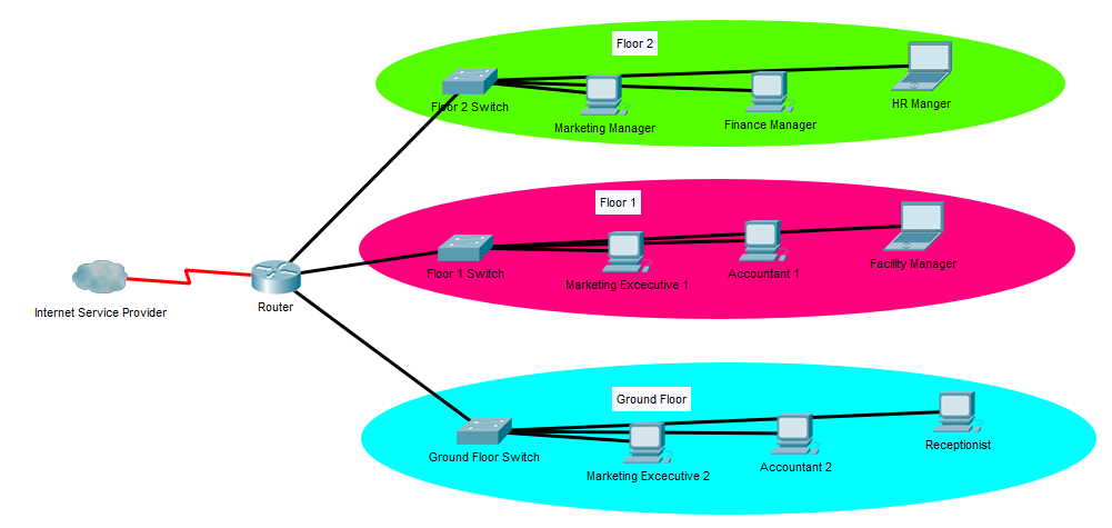
As you can see, this segmentation is not an effective way to network policing because employees belong to different departments are located on the same floor. If this office LAN physically segments based on the departments, the network will be a mess of cables and hard to maintain as explained above.
VLAN Segmentation
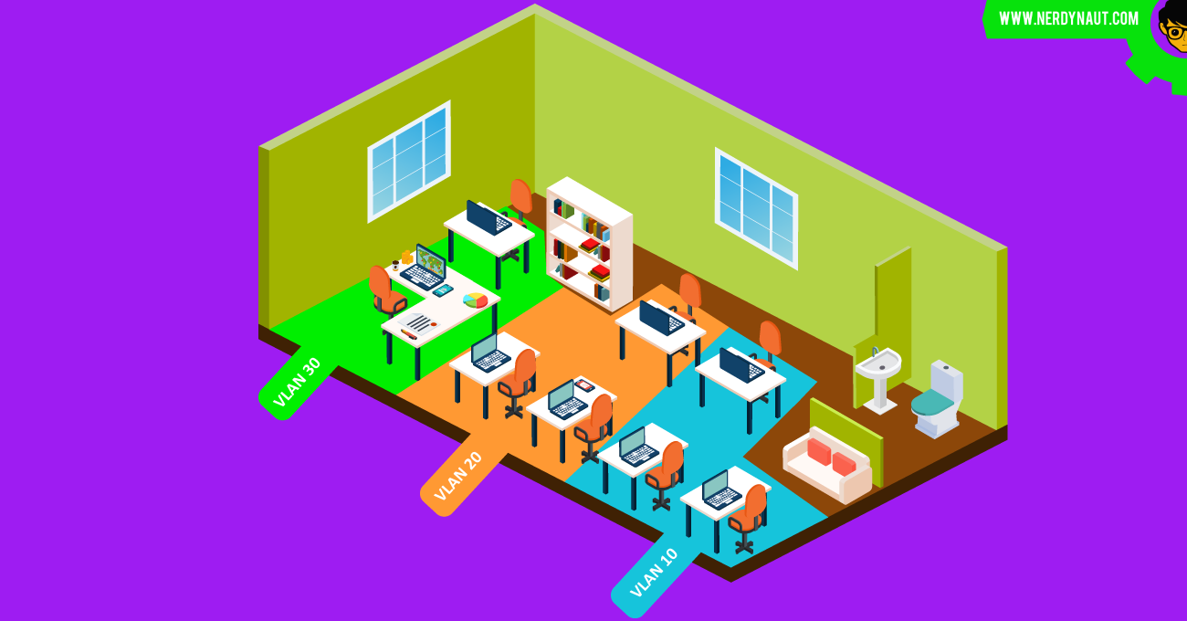
The usage of VLANs accountable to overcome above mentioned high maintenance, costly and hard to manage network scenario, by grouping the network users using logical networks which are called VLANs by keeping the same physical network topology. Nowadays VLANs are used in any kind of company and when it comes to wireless networks VLANs are truly crucial technology to be applied for segmenting the users to achieve network policing. Almost any network switch which is available in the market now supports VLAN segmentation. An office LAN with the VLAN segmentation has been represented in the following figure.
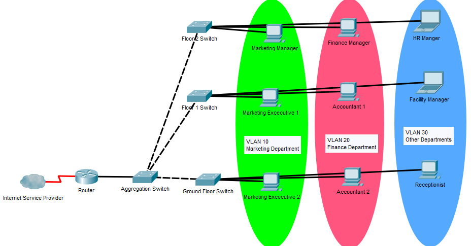
The networking team can group the end devices and the traffic originated from them in any desirable criteria without any doing any physical change to the topology. There are many other advantages of using VLAN segmentation.
LANs and VLANs Concepts Simplified
Still confused about VLANs. Let’s use a simple story to understand all these concepts in a different manner. But feel free to skip this story time if you have already mastered the VLAN concept. The story is about a farmer named Dekker. Dekker is into poultry farming and his little farm is located next to his home. At moment there are 30 hens on the farm and there is plenty of extra space to triple the number of hens. A few days ago Dekker got married to Maria. Maria’s father gave 10 pigs yesterday to Dekker as a part of the promised dowry for marrying his loving daughter. Dekker kept those pigs in the poultry farm because there is enough space to farm the pigs also there. Today morning, Dekker wake up and went to feed the animals. Suddenly, Dekker was shocked. Most of the eggs that have laid by the hens yesterday night have been trodden by the pigs. After a few seconds, Maria came there and said to Dekker that pigs have known to kill and eat hens as their fresh meal. After serious thinking about this situation, Two solutions came to Dekker’s mind. They are,
- Building a new farm for Cows: This method needs a significant amount of money and Land. Dekker also has to set up water and power separately for the new farm. He will have to carry food and other equipment (Especially the tools to dispose of animal’s solid wastage) to two locations. As a conclusion, More cost (building + maintaining), doubled the tasks to do.
- Separating the existing farm into two parts using a wooden wall – This is the most suitable solution for Dekker. Because the cost of a wooden wall is very small compared to the cost of building a new farm. There will be no wars between pigs and hens. Dekker can do the farming tasks in the same location, no more additional power costs and equipment purchasing. More importantly, Dekker doesn’t need to use the land where he grows pumpkins for building another farm. This solution is a win-win situation for all.
Now is the time to get rid of silly story figures and get back to the networking mode. The existing farmhouse of Dekker is a LAN where there is also a gateway (door) go out or go in like the router port in a LAN. Hens and Pigs are end users of two departments in an office who has different needs to use the network and there is a security threat that can occur when they work together without network policing. Dekker represents the computer networking team at the office. The tragedy happened to the eggs of hens demands the necessity of LAN segmentation. The first solution of Dekker which is to build another farmhouse is the physical segmentation or the traditional segmentation that we discussed earlier. The second solution that uses a wooden wall is the VLAN segmentation. The wooden wall separates the animals but can be removed and replace in another direction easily as VLANs.
Another important concept can be understood in this story. When the pigs and hens live together without a wall. Both pigs and hens have access to resources like water, food of hens and food of pigs. This is similar to the broadcast domain in the netowrking environment. But with the LAN segmentation, pigs will have only their food and hens will have only what they need.
How do VLANs work
Each VLAN belongs to a sperate broadcast domain and belongs to an IP network that unique in the LAN using private or public IP addressing. End devices in the same VLAN can communicate with each other and end devices belong to different VLANs can not communicate unless there is an inter-VLAN routing process happening by a router or a Layer 3 switch. Inter-VLAN Routing is another topic to discuss. But as a summary, the three methods that inter VLAN routing can happen is mentioned below.
- Traditional inter-VLAN routing – One router interface dedicated to one VLAN. If there are 10 VLANs, LAN must be connected to 10 router interfaces.
- Router-On-A-Stick – All the VLANs shares one router Interface to do the inter-VLAN routing. Each VLAN will have a sperate subinterface. Subinterfaces are logical interfaces which run within a physical interface.
- Inter-VLAN Routing using Layer 3 Switch – Layer 3 switches has the capability of routing. Inter-VLAN routing can be done by using these kinds of devices. This method is the best option for large scale networks to reduce the workload of the routers.
The switch ports that have connected to end devices must be configured to “Access” mode where the traffic belongs to only one specific VLAN can flow through the port. The ports that connect between switches are configured to “Trunk” mode where the traffic belongs to any VLAN can be pass through. In this process, the switch uses VLAN tagging/encapsulation protocols. IEEE 802.1Q encapsulation is the most common method used for VLAN trunking and there is another protocol, Inter-Switch Link (ISL) protocol which is a proprietary protocol by Cisco. 802.1Q use a 4-bytes long header space from the Ethernet frame header to indicate the VLAN Identifier of the VLAN that the Ethernet Frame belongs to. Trunking is also another topic to discuss in a wide manner.
The VLAN identifier is another important fact in VLAN technology. The VLAN identifier is a number between 0-4095. This can be divided into two sections as Normal Range and Extended Rage. These two groups are compared in the following table.
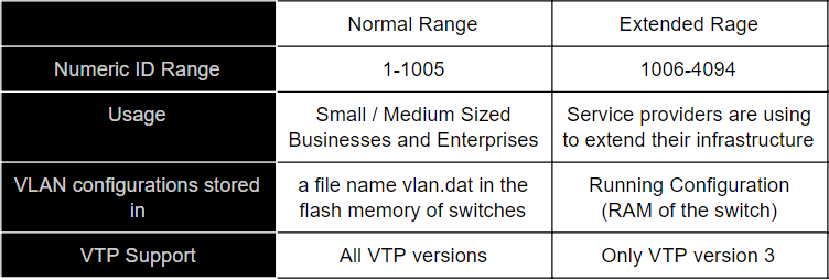
VLAN 0 and 4095 are reserved for system usage and not visible for network administration. VLAN 1 and 1002-1005 are automatically created by the device and can not be removed. VLAN 1002, 1003, 1004 and 1005 are dedicated for legacy networking protocols like FDDI and Token Ring. Those VLANs cannot be used for any other purpose.
Apart from that, VLAN Trunking Protocol (VTP) and Dynamic Trunking Protocol (DTP) can be to configured to enhance the productivity of using the VLAN technologies. Both of these protocols are developed by Cisco as proprietary solutions. VTP is used to automate the creation, deletion and synchronization of VLAN across multiple switches. DTP is the protocol to automate negotiating the trunking process between switch ports.
Advantages of VLANs
VLANs provide a lot of advantages to a network. The major advantages of VLANs are described below.
- Reduction of Cost – Usage of VLANs reduces the number of switches to be used in the network to achieve the networking goals and reduce the number of required router ports to the minimum. Ethernet cabling also can be implemented in a simpler way and that minimize the network cabling cost.
- Higher Performance – VLANs segment the single broadcast domain of the physical LAN into smaller broadcast domains. This reduces the network overhead of each switching device and provides a speedy and efficient data flow across the network.
- Enhanced Security – VLANs gives the ability to carry out a solid network policing by segmenting users into different groups. This is a great precaution for data breaches and other threats for information security.
- Higher Scalability – A new device can be added to anyplace in the network and configure its connected switch port to any desired VLAN without much effort. The number of devices that can be connected to a particular VLAN is depended on the size of the IP block that is used in the VLAN. But the IP block can be changed to a larger block by executing a couple of commands and connect the desired number of devices to the network.
- Better Manageability and Maintainability – Activities like upgrading the network, network policing, network designing, replacing network devices and network troubleshooting will be much easier with the usage of VLAN Technologies.
Disadvantages of VLANs
VLANs are a very useful technique which is a mandatory concept to be applied in good network designs unless the network has only a few end devices. However, the maximum number of VLANs is 4096 and only 4090 VLANs including the VLAN 1 is practically usable for network administration. This fact can be highlighted as a limitation of VLANs. But it’s not practical to even reach this limit as an enterprise.
In another perspective, Usage of VLAN requires the router’s accountability to carry out internal data flow between devices belongs to different VLANs. That can increase the workload of the router. This may be considered as a disadvantage of VLANs but the usage of Layer 3 switches mitigates this problem.
Types of VLANs
There are a few types of VLANs to be concerned to understand the practical procedure of VLANs in a network. The types of VLANs are described below.
- Default VLAN – Default VLAN is already configured in the switch as VLAN 1. Most network security engineers tend to change the default VLAN from VLAN 1 to another VLAN as a best practice in Security. VLAN 1 cannot be renamed or deleted because it is the device specified default VLAN. In the initial configuration of a switch, all switch ports are assigned to VLAN 1 by default.
- Native VLAN – When an Ethernet frame that flows through a trunking port which doesn’t belong to any configured VLAN, that frame will be assigned to the native VLAN. This traffic is called Untagged Traffic.
- Management VLAN – This VLAN is configured to access the management services of a switch. This VLAN is used by the IT Team for network management. In Cisco switches VLAN 1 also serving as the management VLAN by default.
- Voice VLAN – The VLAN that is dedicated to transport the voice packets of IP Telephone Network which is implemented using Voice Over IP (VOIP) technology is called as the Voice VLAN.
VLAN Configuration
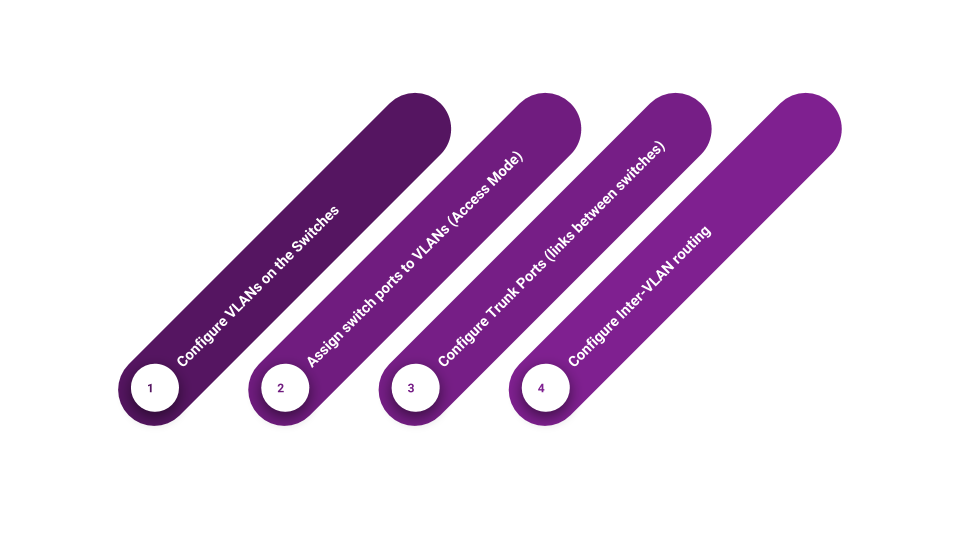
VLAN configurations are very simple and easy. The main steps of basic VLAN configuration are mentioned below.
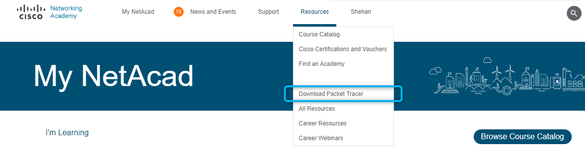
The best way to get to know each of these steps is going through a practical network configuration. The following tutorial is about the basic VLAN configuration using Cisco networking devices. You can do this practical using physical devices. But it is not a possible option for everyone. Cisco Packet Tracer is the best option to try out this practical virtually. If you do not have install Packet tracer in your computer. You can download it from the official website of Cisco Networking Academy for free. All you need to do is get registered and log in on the site and click on the following link in the navigation bar.
By referring “Introduction to Packet Tracer” free online course by Cisco, you will be able to master this tool within 10 hours.
Basic Configuration
Let start our VLAN configuration exercise now. Set up the following topology on Packet Tracer by dragging and dropping the required devices. Cables that represented by dashed lines are crossover cables, straight lines represent straight-through cables. Use 2960-24TT model Switches and 1941 Router.
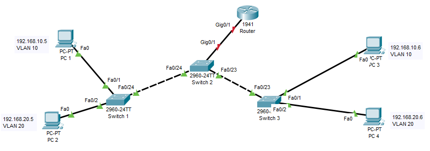
After setting up the topology let’s configure IP addresses of all the PCs by referring the following table.
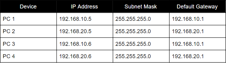
If you are wondering how to do the IP configuration in a PC, please follow these steps.
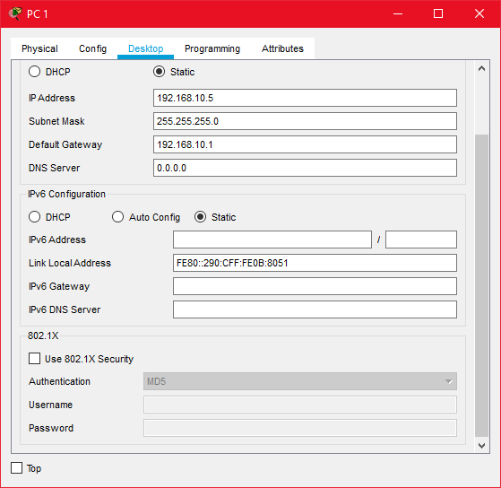
Click on the PC icon > go to “Desktop tab” > Click on “IP Configuration”
Make sure the “Static” option is selected. Put correct IP details in the correct form as below. Don’t do any changes to any other field other than IP Address, Subnet Mask and Default Gateway. After giving correct details, Close the IP Configuration Windows.
All the basic works are done after configuring the IP addresses to all PCs. Now we can start configuring switches.
Click on a switch and click on “CLI” tab and press “Enter button”.

This is the time to start configurations in the command way. After typing each command you have to press “Enter Button” to execute the command. If the command is wrong, the CLI will prompt you an error message saying the command is invalid. Let’s start the job then. Please repeat the following steps in all three switches.
First, you have to go to enable mode.
Switch> enable
Then you have to go to Global Configuration Mode.
Switch#configure terminal
As a best practice, it is better to disable all interface with the shutdown command at the beginning of a fresh configuration.
Switch(config)#interface range fastEthernet 0/1-24
Switch(config-if-range)#shutdown
Switch(config)#exit
Switch(config)#interface range gigabitEthernet 0/1-2
Switch(config-if-range)#shutdown
Switch(config)#exit
Configuring VLANs on the switches
After the basic configurations, we are ready to configure the VLANs using the following commands. We have two VLANs as VLAN 10 and VLAN 20 to be configured. VLAN 10 is for marketing employees and VLAN 20 is for finance employees.
Switch(config)#vlan 10
Switch(config-vlan)#name Marketing
Switch(config-vlan)#exit
Switch(config)#vlan 20
Switch(config-vlan)#name Finance
Switch(config-vlan)#exit
You can verify that using the configuration using ‘show vlan’ or ‘show vlan brief’ commands in enable mode. You must have the same report as below.
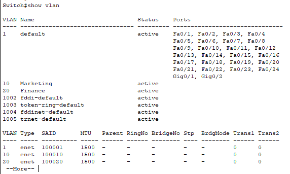
Repeat the same steps in Switch 1, 2, 3.
Configuring the access ports
Access ports are switch ports that connect to end devices. In our topology only Switch 1 and Switch 3 are connected to end devices. Therefore following VLAN assigning commands should be configured only on those switches.
Switch(config)#interface fastEthernet 0/1
Switch(config-if)#switchport mode access
Switch(config-if)#switchport access vlan 10
Switch(config-if)#no shutdown
Switch(config-if)#exit
Switch(config)#interface fastEthernet 0/2
Switch(config-if)#switchport mode access
Switch(config-if)#switchport access vlan 20
Switch(config-if)#no shutdown
Switch(config-if)#exit
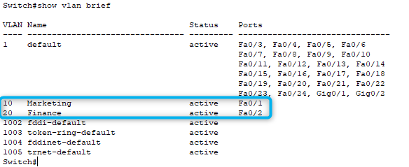
These commands have configured in the interface configuration level and the first switchport command is to enable access mode on the interface and second command is to assign the interface to a specific VLAN. Finally, you have to enable to interface with the ‘no shutdown’ command. After implementing access ports, Switch 1 and Switch 2 configurations can be verified as below.
Configuring Trunk Ports
Links that should carry the traffic belongs to any VLANs should be configured in the Trunk mode. Links between switches, Link between router and switches should be turned into this mode. Since we have used different interfaces to connect switches, the configuration on every switch is not the same. Carefully, implement the following commands in the correct switch.
Switch 1
Switch(config)#interface fastEthernet 0/24
Switch(config-if)#switchport mode trunk
Switch(config-if)#switchport trunk allowed vlan all
Switch(config-if)#no shutdown
Switch(config-if)#exit
Switch 2
Switch(config)#interface fastEthernet 0/24
Switch(config-if)#switchport mode trunk
Switch(config-if)#switchport trunk allowed vlan all
Switch(config-if)#no shutdown
Switch(config-if)#exit
Switch(config)#interface fastEthernet 0/23
Switch(config-if)#switchport mode trunk
Switch(config-if)#switchport trunk allowed vlan all
Switch(config-if)#no shutdown
Switch(config-if)#exit
Switch(config)#interface gigabitEthernet 0/1
Switch(config-if)#switchport mode trunk
Switch(config-if)#switchport trunk allowed vlan all
Switch(config-if)#no shutdown
Switch(config-if)#exit
Switch 3
Switch(config)#interface fastEthernet 0/23
Switch(config-if)#switchport mode trunk
Switch(config-if)#switchport trunk allowed vlan all
Switch(config-if)#no shutdown
Switch(config-if)#exit
These commands also have to be implemented in the interface configuration mode. First switchport command is to enable the trunks and second is to let all VLANs to be trunked via the port. That command is already configured by default. Anyways, it is better to type that command also as a best practice. Finally, the interface should be enabled using no shutdown command.
Now the basic VLAN configurations are almost done. We can test the network with VLAN rules.
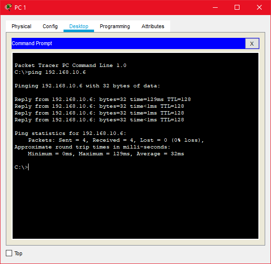
The PCs that are in the same VLAN should have a successful ping. In our case, PC1 should be able to ping PC3 and PC2 should be able to Ping PC 4.
A ping can be performed by clicking the PC icon > click the “Desktop” tab > click on the “Command Prompt” icon > then type the correct destination IP as below.
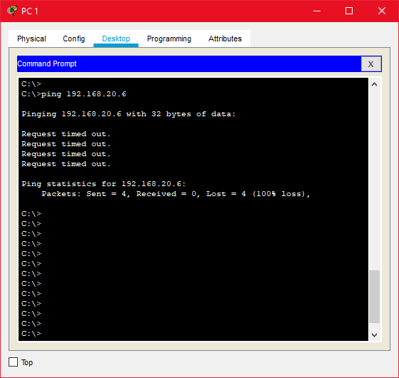
But ping between PC1 and PC4 should be failed because those PCs belong to different VLANs.
Configuring Inter-VLAN Routing
Inter-VLAN routing should be configured to let PCs in different VLANs to communicate with each other. As noted earlier, there are three ways to perform inter-VLAN routing. In our tutorial, we are going to use Router-On-A-Stick method which uses only one router interface with 802.1Q tagging.
Please go to the CLI of the router and configure the following commands in global configuration mode on the router.
Router(config)#interface gigabitEthernet 0/1.10
Router(config-subif)#encapsulation dot1Q 10
Router(config-subif)#ip address 192.168.10.1 255.255.255.0
Router(config-subif)# exit
Router(config)#interface gigabitEthernet 0/1.20
Router(config-subif)#encapsulation dot1Q 20
Router(config-subif)#ip address 192.168.20.1 255.255.255.0
Router(config-subif)# exit
Router(config)#interface gigabitEthernet 0/1
Router(config-if)# no shutdown
Router(config-if)# exit
In this configuration, we have to create two subinterfaces as 0/1.10 and 0/1.20 for the two VLANs we are using in the network. After that, we have to mention the VLAN related to each subinterface and IP address of each subinterface, which is working as the default gateways of each VLAN. Finally, the physical interface (0/1) should be enabled with the ‘no shutdown’ command.
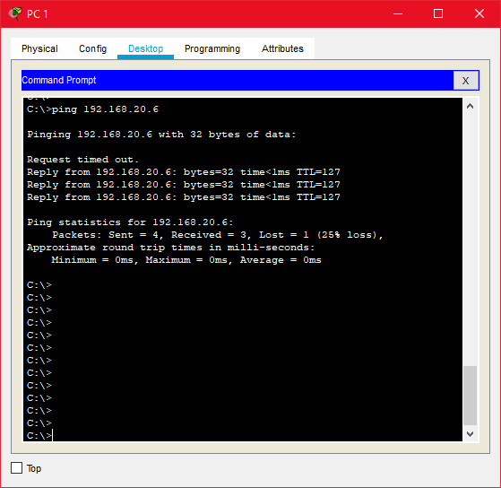
Now your Job in the topology is 100% completed. You may able to ping from PC1 to PC3 Now.
Hope you enjoyed the concepts behind the VLANs in Computer Networking. Please read and practice more about these topics and become a Network Engineer / Architect / Administrator with a solid conceptual understanding and practical exposure.


